Format lines and connectors
Once you draw a line or connector (see Add lines and connectors), you can format its appearance.
1. Select the line or connector and click the properties button ![]() . The properties panel opens.
. The properties panel opens.
2. Make adjustments to the format, using the following table as reference.
| Property | Icon | Description |
|---|---|---|
|
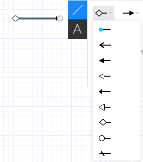
Arrow Begin Arrow End |
|
Specify the direction of the line by adding an arrow at the end. The direction in which the arrows points in these properties translate as: left = line start point and right = line end point. So if you draw your line from right to left, and you select the arrow that points to the right, your line will have an arrow pointing to the left. Consistently drawing your lines and connectors from start to end will make adding arrows much easier. Specific lines, such as UML, ERD, or BPMN, provide additional arrow ends, specific to that shape type.
|
| Line Color |
|
Specify the color of the line. |
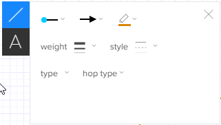
| Line Weight |
|
Specify the thickness of the line. |
| Line Style |
|
Specify the pattern for lines and connectors, from dotted to solid. |
| Line Type | Specify the type of line of connector. The first option in the list is a straight line. The next three are connectors with right angle, rounded corner, and Bézier curve. | |
| Hop Type | Specify the line's format when it crosses, or hops, on top of another line. |